
|
Model 526 |
|
|
|
|
|
|
| ||||||||||||||||||||
|
|
|
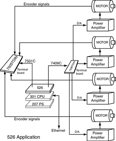
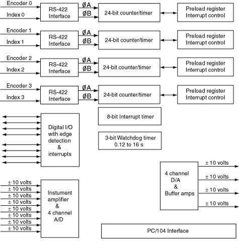
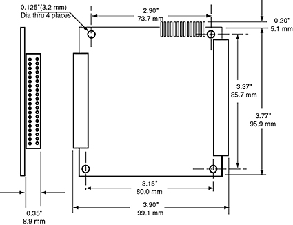
Description Model 526 measures incremental encoders pulses, analog voltages and detects digital signals. It also generates analog voltages, digital outputs and has a watchdog timer and an interrupt timer. Encoder Counters Counters may be configured as timers by counting pulses from an internal clock of 27 or 13.5 MHz. Timers can generate a single-shot pulse or a pulse width modulated waveform at one of the digital outputs. Watchdog Timer The A/D converter is factory calibrated by storing the actual value of the on-board 10 V reference in the EEPROM. Digital I/O DC/DC Converter Images and Mechanical Drawings | |
 |
|
 |
|
 |
|
| Specifications | |
| Power input | 5 volts, 280 mA |
| I/O ports | 27 ports |
| A/D range | ±10 volts |
| A/D resolution | 305 uV |
| A/D throughput | 10 kHz one channel |
| A/D noise | 2 sigma = 4 counts |
| A/D format | 2’s complement |
| D/A range | ± 10 volts |
| D/A resolution | 305 uV |
| D/A throughput | 10 kHz |
| D/A driver noise | 2 sigma = 4 counts |
| D/A driver current | ± 5 mA |
| Encoder signals | RS-422 clockA, clockB, index,5 V |
| Counter type | Four 24-bit synchronous up/down with preload, interrupts |
| Encoder count rate | 10 MHz at 1x, 5 MHz at 2x, 2.5 MHz at 4x |
| Digital I/O | 8 lines with outputs connected to inputs |
| Output drive current | 25 mA |
| Output sink current | 25 mA |
| Input pullup resistor | 10 k ohm |
| Edge detection | State change 0 to 1, 1 to 0 |
| Watchdog timer | 0.125 to 16 seconds |
| Interrupt timer interval | 100 us to 25.5 ms |
| Ordering Information | |
| Model 526 | Multi I/O module with A/D |
| Model 301-6 | PC/104+ CPU |
| Model 207 | PC/104 Isolated power supply |
| Model 7409C | Analog I/O 18” flat cable |
| Model 7409C1 | Analog I/O 1 meter flat cable |
| Model 7506TDIN | 40 contact terminal board |
| Model 7501C | Digital I/O 18” flat cable |
| Model 7501C1 | Digital I/O 1 meter flat cable |
| Model 7505TDIN | 50 contact terminal board |
