Analog & Digital Interface

Model 425

Rectangle
Model 425

Features
Three quadrature encoder channels with 24-bit counters

Four 12-bit D/A outputs

Eight 12-bit differential A/D inputs, 50 kHz rate

Watchdog timer

Forty-eight bidirectional digital signals for solid state relay boards

16 Programmable Interrupts for counters and digital I/O

PC/ISA compatible

Rectangle

Description
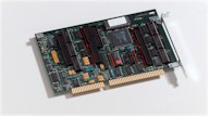
The Sensoray Model 425 low cost interface saves space in ISA bus systems by combining five functions into a half-size module. Four flat cables connect the Model 425 to external breakout boards.

Encoders
The 24-bit up/down counter channels are optimized for incremental encoders. Each channel accepts two phased TTL or RS-422 signals, plus an index signal, to track encoder direction and displacement. Unlike conventional counters, the 425 counters do not accumulate errors when the encoder dithers or changes direction. The 425 supplies 5-volt power to all encoder channels. Each counter can be programmed to function as an encoder interface or as a general-purpose timer and may optionally generate interrupts. To ensure maximum flexibility, no counter functions are used by any other on-board peripheral devices.

 A/D
Eight differential input channels are multiplexed to a sample/hold amplifier and high-speed A/D converter. A resistor-programmable instrumentation amplifier allows gains of 1 to 1000. An on-board DC/DC supply ensures A/D linearity for + 10-Volt input signals.

Picture

D/A
Four voltage outputs channels may be programmed for 0 to +10 volts. One channel has a remote sense input to minimize line loss errors. All outputs are automatically reset to zero volts whenever a bus or soft reset occurs.

 Watchdog
The 425's watchdog timer output may be routed to either bus reset or nonmaskable interrupt. It may be enabled or disabled under program control. The timer is automatically disabled whenever a bus reset occurs.

Digital I/O
The Model 425 has forty-eight high-current digital I/O channels with connector pinouts designed for direct connection to industry- standard solid relay boards. Each line is software programmable as either input or output. Sixteen of the channels may be programmed for edge detection and interrupts. Read-back circuitry enables the physical state of output lines to be monitored. Whenever a system reset occurs, all output channels are automatically turned off.

Rectangle
Rectangle
Specifications
 General
Operating temperature -25C to +70C
PC bus interface I/O mapped, 64 ports
 Input power < 3 watts
 A/D Converter
Number of channels 8 differential
Input resistance 100 MW
 CMRR 100 dB min
Max common mode +5 volts
Conversion time 20mS
Resolution 14-bits
Input voltage range 0 to 10 V, +5 V
Offset error +1/2 LSB
D/A Converter
Conversion time 20mS
Resolution 14-bits
Offset error +2 LSB
Voltage output 0 to +10 volts
Output resistance 87W
Digital I/O
Number of channels  48 bidirectional
Output voltage 0 to +5 V open collector
Output sink current 100 mA @ 1.1 V
Encoder I/O
Number of channels 3 quadrature, 24-bit
Input voltage TTLor RS-422
Input frequency 350 kHz
Ordering information
Analog I/O
18" analog cable, 40-pin 7409C
1 meter analog cable, 40-pin 7409C1
Low cost analog screw terminal board 7409TB
Screw terminal board with proto area 7409TC
Screw terminal board with proto area and DIN snap rails 7409TDIN
Digital I/O
18" digital cable, 50-pin  7501C
 1 meter digital cable, 50-pin 7501C1
 24 position relay board w/o DIN 720RB
 24 position relay board
 with DIN snap rails
720RBDIN
 Encoder
18" encoder cable, 20-pin 7502C3
 1 meter encoder cable, 20-pin 7502C4
 Terminal board w/o DIN rails 7502TA
Screw terminal board with DIN snap rails 7502TDIN

Watchdog Timer
Time-out: Software programmable for 500 mS or 12 seconds
2-pin connector may be connected to the bus reset line to allow a system reset from software.

Rectangle